Routing at the core
A Cisco 3560 routes between HQ VLANs using switched virtual interfaces. Two Cisco 2960 access switches connect eight PCs, while the central server occupies a dedicated server VLAN.
PROJECT / 03 · ENTERPRISE NETWORKING
PHASE 1 · IMPLEMENTEDAn enterprise network connecting Swansea headquarters and the Cardiff branch. Built in Cisco Packet Tracer with departmental VLANs, efficient IPv4 addressing, dynamic routing and centrally managed DHCP.
Connect two offices while keeping departments in separate broadcast domains. Give clients at both sites their addresses from a single Swansea server, and exchange routes dynamically between the sites. Preserve the completed Phase 1 simulation as the baseline for a later resilience phase.
A Cisco 3560 routes between HQ VLANs using switched virtual interfaces. Two Cisco 2960 access switches connect eight PCs, while the central server occupies a dedicated server VLAN.
A Cisco 2911 provides the branch VLAN gateways over an 802.1Q trunk to the access switch. Four PCs connect locally, and DHCP requests are relayed to Swansea over the Ethernet WAN.
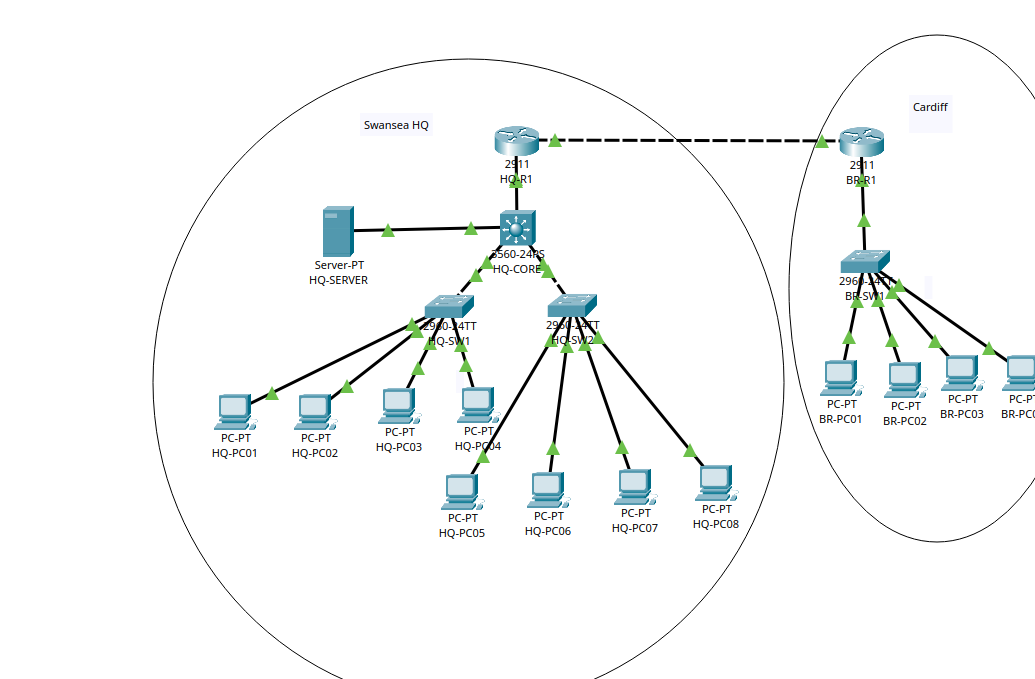
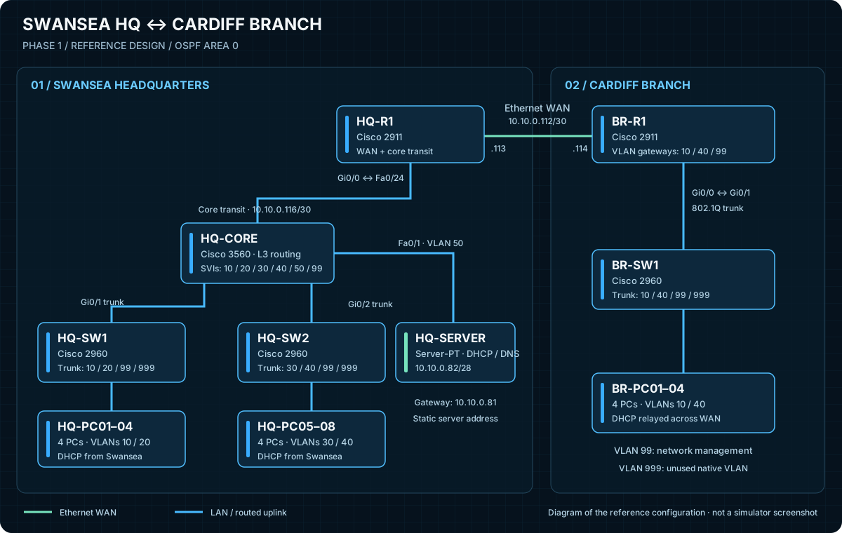
The physical port map is included in the architecture document.
The reference design uses different subnets at each site, even where VLAN IDs are shared. Each VLAN gateway uses its first usable address. Network management uses VLAN 99; server addressing is static.
| VLAN | Swansea subnet | HQ gateway | Cardiff subnet | Branch gateway |
|---|---|---|---|---|
| 10 | 10.10.0.0/27 | 10.10.0.1 | 10.20.0.0/27 | 10.20.0.1 |
| 20 | 10.10.0.32/27 | 10.10.0.33 | — | — |
| 30 | 10.10.0.64/28 | 10.10.0.65 | — | — |
| 40 | 10.10.0.128/26 | 10.10.0.129 | 10.20.0.32/27 | 10.20.0.33 |
| 50 · Server | 10.10.0.80/28 | 10.10.0.81 | — | — |
| 99 · Management | 10.10.0.96/28 | 10.10.0.97 | 10.20.0.64/28 | 10.20.0.65 |
ETHERNET WAN10.10.0.112/30
CORE ↔ HQ ROUTER10.10.0.116/30
CENTRAL SERVER10.10.0.82/28
HQ-CORE, HQ-R1 and BR-R1 exchange the site networks through OSPF. The routed core uplink and Ethernet WAN establish neighbour relationships; client-facing interfaces are passive.
The Swansea server provides six client pools. Helper addresses on the HQ SVIs and branch router subinterfaces forward DHCP requests from each client VLAN. Management and server addresses are reserved outside the client pools.
The reference configurations include SSH with local login, management access restrictions, limited trunk VLANs, unused-port shutdown and endpoint port security. Credentials are replaced with placeholders in the downloads.
Phase 2 will explore redundant paths, gateway or switching redundancy and failover testing. The direct WAN and single core remain deliberate single points of failure in the Phase 1 baseline.
An SVI on HQ-CORE routes VLAN 10 and forwards DHCP broadcasts to the central server.
interface Vlan10
 ip address 10.10.0.1 255.255.255.224
 ip helper-address 10.10.0.82
no shutdownThe branch gateway tags VLAN 40 traffic on its switch-facing link.
interface GigabitEthernet0/0.40
 encapsulation dot1Q 40
 ip address 10.20.0.33 255.255.255.224
ip helper-address 10.10.0.82Only the two transit interfaces establish OSPF adjacencies.
router ospf 1
 router-id 2.2.2.2
 passive-interface default
 no passive-interface GigabitEthernet0/0
 no passive-interface GigabitEthernet0/1
 network 10.10.0.116 0.0.0.3 area 0
network 10.10.0.112 0.0.0.3 area 0Explore the six device templates, server instructions and build documentation. These are the references prepared for the project; final running-configuration exports and recorded test outputs are not included. Department descriptions in the templates are suggested labels.
The templates contain password placeholders. Replace them privately before reuse and check command support against your Packet Tracer device models.
Phase 1 is complete following implementation and DHCP troubleshooting. The verification plan covers same-VLAN and inter-VLAN connectivity, bidirectional site access, OSPF neighbours and routes, central DHCP, management access and configuration persistence. The topology screenshot is included above; captured command outputs and individual test results will extend the evidence.
Interested in the topology or my infrastructure experience?